
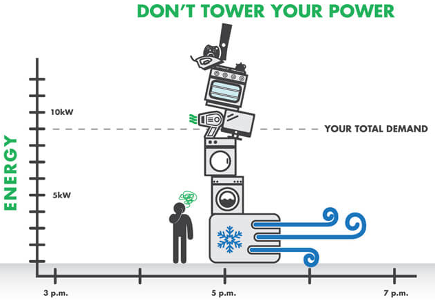
Co-ordination
Co-ordination: what does it mean?
Co-ordination means ensuring that the operating characteristics of a protective device (such as a circuit breaker or fuse) are correctly adjusted in relation to the electrical conductor, so as to protect it against possible overloads. In other words, it is the alignment of the load, maximum demand, protected device and the current carry capacity to ensure that the system operates safely, meeting the conditions specified in AS/NZS3000, clause 2.5.3.1.
A practical example of the importance of coordination in a residential installation is the overload protection of the kitchen socket circuit. Let’s assume that this circuit is designed to support a maximum current of 20 A, with a cable sized for this capacity. The circuit breaker protecting this circuit must also be set to trip when the current exceeds this limit.
Why is it important?
If the circuit breaker is incorrectly sized, for example, set to 25 A, it may not trip in the event of an overload. This means that if too many appliances, such as a microwave, coffee maker, toaster etc, are turned on at the same time, the current in the circuit may exceed the 20 A supported by the cable. In this case, the cable may overheat, damage its insulation and, in the worst case scenario, cause a fire.
Risks of lack of coordination:
-
Overheating of cables: Can damage insulation and expose conductors, increasing the risk of short circuits and electric shocks.
-
Fires: Undetected overloads can lead to prolonged overheating and eventually flames.
-
Faults in electrical devices: Equipment connected to the circuit can be damaged by high current.
-
Reduced service life of the installation: Without adequate protection, wiring and devices are subject to premature wear.
Therefore, ensuring coordination between the protection devices and the conductors is essential for the electrical safety of the installation, preventing damage to the system, connected equipment and, most importantly, protecting the integrity of residents.
The operating characteristics of a device protecting a conductor against overload shall satisfy the following two conditions:
. 2.1 IB ≤ IN ≤ IZ
. 2.2 I2 1.45 x IZ
- IB = the current for which the circuit is designed, e.g. maximum demand.
- IN = the nominal current of the protective device.

- Z = the continuous current-carrying capacity of the conductor
- I2 = the current ensuring effective operation of the protective device and may be taken as equal to either—
(a) the operating current in conventional time for circuit- breakers (1.45 IN) = ; or
(b) the fusing current in conventional time for fuses (1.6 IN for fuses in accordance with the IEC 60269 series).
Below are the clauses that address this issue:
2.5.3 Protection against overload current
2.5.3.1 Coordination between conductors and protective devices
Current carrying capacity
Current Carrying Capacity refers to the maximum current that an electrical conductor (such as a cable or wire) can carry continuously without its temperature exceeding the safe limits specified by the conductor material and its insulation.
In simple terms, it is the safe limit of current that the cable can carry without overheating or causing damage to the electrical installation.
Table 1 of AS/NZS 3008.1.1 is typically used for most calculations, provided the cable operates within the maximum allowable temperature limits.
For thermoplastic or XLPE cable first determine the installation method from tables
- 3(1) unenclosed in air
- Refers to cables installed on supports or suspended in the air, without ventilation restrictions.
- Generally allows greater heat dissipation, resulting in greater current capacity.
- 3(2) enclosed
- Refers to cables installed in ducts, conduits or enclosed spaces.
- Reduced ventilation may limit heat dissipation, reducing current capacity
- 3(3) buried direct in ground
- Cables installed directly in the ground, usually in a bed of sand or similar.
- Current capacity depends on the thermal conditions of the ground.
- 3(4) buried in enclosure
- Cables installed in ducts or enclosures buried in the ground.
- May limit heat dissipation compared to direct installation in the ground.
On the table, the columns are organized by
- Item number
- Cable details (two or three core)
- Reference drawing
- Current-carrying capacity table reference
- Methods of installation for cables deemed to have the same current-carrying capacity
- Derating table
Below is an example of selecting the appropriate 4-core + E unarmored V75 Circular Cu cable, with insulation installed using the method “clipped directly to a vertical surface and open to air,” protected by a circuit breaker (CB), for a sub-main circuit designed to handle a maximum demand of 172A.
Circuit breaker: 200A
- The cable will be opened to air, so table 3(1).
- Check column 5 for the description that applies for it, item 13.
- Cables installed — (a) clipped direct to a wall, floor, ceiling or similar surface;
- Double check on colun 2 if it is three core
- Confirm in column 4 which table and column should be checked to find the CCC value, Tables 13 and columns 5.
- The selection of the cable should be based on the current carry capacity of the cable, so that means for the protection of a device selected as 200A the cable needs to satisfy the form IN ≤ IZ, in this case the cable selected is 95mm, once it is capable to carry 213A (200 is ≤ 213).
A sub-main cable Maximum demand: 172A 4 core + E unarmored V75 Circular Cu Insulation methond clipped directly to a vertical surface open to air protected by CB
Answer:
cb 200A Table select 13(1) -> Item 13 -> Selected table 13 Columns 5 The selection of the cable should be based on the current carry capacity of the cable, so that means for the protection of a device selected as 200A the cable needs to satisfy the form IN ≤ IZ, in this case the cable selected is 95mm, once it is capable to carry 213A (200 is ≤ 213).
Voltage drop
Voltage drop
On the book AUSNZS 3000, clause 3.6.2 says:
“The cross-sectional area of every current-carrying conductor shall be such that the voltage drop between the point of supply for the low voltage electrical installation and any point in that electrical installation does not exceed 5% of the nominal voltage at the point of supply.”
Electrical equipment is designed to operate within a specific voltage range (e.g. 220-250 V AC). An excessive voltage drop in a circuit can reduce the voltage available to the load, causing the equipment to operate outside its optimal range. This can result in malfunction, reduced efficiency, overload or even permanent damage to the device, compromising its useful life and the safety of the electrical installation.
Therefore, VD is a fundamental concept for electrical installations to ensure the correct functioning of the network and:
- Equipment Performance
When the voltage at the terminals of a piece of equipment is lower than specified (due to voltage drop), performance may be impaired.- Electric motors: may lose efficiency, generate less torque or overheat.
- Light bulbs: may illuminate with less intensity.
- Electronic equipment: may fail or operate improperly.
-
Energy Saving
Excessive voltage drop results in energy losses in the cables (in the form of heat). This increases the total energy consumption and reduces the efficiency of the system. - Safety
A high voltage drop can lead to overheating of conductors, especially in undersized installations, increasing the risk of:- Electrical fires.
- Damage to cable insulation.
- Standards Compliance
Electrical standards (such as AS/NZS 3000 in Australia) set limits on voltage drop, typically around 5% of nominal voltage for low voltage installations.
- This ensures that the voltage at the most distant points of an installation is sufficient for the proper operation of equipment.
- Conductor Sizing
The calculation of voltage drop directly influences the choice of conductor gauge (cross-section).
- Thicker cables have lower resistance and, therefore, less voltage drop.
- Correct sizing avoids unnecessary expenses with oversized conductors and ensures economic and technical efficiency.
- Long Distances In long circuits, voltage drop is even more relevant because the cable resistance increases proportionally to the length. It is essential to correctly size the cables to avoid problems.
Calculating Voltage Drop
The mV/A.m value represents the number of millivolts dropped when a current of one ampere flows in a one metre length of cable. The following equation can be used to determine the voltage drop in a given circuit:
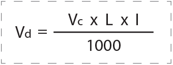
Where:
Vd = voltage drop in volts (V)
Vc = three phase millivolts per ampere-metre (mV/A.m)*
L = route length of the circuit conductors in metres (m)
I = total load current/maximum demand of the circuit in amperes (A)**
* To determine voltage drop in a single phase circuit, the three phase values of Vc must be multiplied by a factor of 1.155.
** AS/NZS 3000:2018 Clause 3.6.2 Exception 1 states that half of the circuit protection device nominal current rating may be used for calculating voltage drop on circuits where the load is distributed across the length of the circuit, such as with socket outlets and lighting circuits.
Example
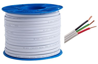
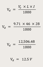
A 400 V three phase final subcircuit has a maximum demand of 28 A, a route length of 46 m, and is supplied by a 4 mm2 multicore V-90 TPS Cu cable. Determine the voltage drop in the final subcircuit.
The first step is to find the value of Vc from the applicable table in AS/NZS 3008.1.1:2017. In this case, Table 42 is selected based on the type of cable, and Column 6 is selected based on the conductor operating temperature of 75⁰C.
The value of Vc for a 4 mm2 cable operating at 75⁰C is 9.71 mV/A.m.
How can you select the right cable to minimize excessive voltage drop?
To determine the minimum cable size needed to meet a specified permissible voltage drop, the following rearrangement of the equation can be applied:
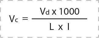
Where:
Vc = maximum permissible value of millivolts per ampere-metre (mV/A.m)
Vd = maximum permissible voltage drop in volts (V)
L = route length of the circuit conductors in metres (m)
I = total load current/maximum demand of the circuit in amperes (A)
The calculated mV/A.m value can then be used to reference the minimum cable size from the relevant table in AS/NZS 3008.1.1:2017.
Example
Select Cables to Satisfy Voltage Drop Limitations
Determine the minimum size cable for a 230 V final subcircuit based on current carrying capacity and voltage drop requirements. The final subcircuit has a maximum demand of 20 A, a route length of 24 m and is to be wired using twin and earth V-90 TPS cable tied to a perforated cable tray with minimum spacing.
The first step is to determine the maximum permitted voltage drop in the final subcircuit.
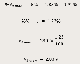
The maximum voltage drop permitted in the cable is 2.83 V. The next step is to determine the minimum cable size based on current carrying capacity requirements. In this case, AS/NZS 3008.1.1:2017 Table 10, Column 2 is used based on the cable and installation method. The minimum cable size based on current carrying capacity is 2.5 mm2, which has a current carrying capacity of 27 A.
The next step is to determine the minimum cable size based on voltage drop limitations. This is done by determining the maximum permitted Vc for the cable.
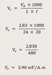
This is a single phase value of Vc and must be converted to a three phase value, as we will be referencing three phase values in AS/NZS 3008.1.1:2017.
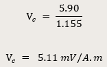
Finally, we find the applicable voltage drop table in AS/NZS 3008.1.1:2017. In this case, Table 42 is selected based on the type of cable, and Column 6 is selected based on the operating temperature of 75⁰C.
The value of Vc for the cable must be less than or equal to 5.11 mV/A.m, which means that the minimum cable size to satisfy voltage drop limitations is 10 mm2, which has a Vc of 3.86 mV/A.m.
Note that in this case, it is likely that the submains and possibly the consumer mains cables would be upsized to assist with reducing the installation voltage drop.
Conclusion:
Coordination between protective devices and conductors, as well as voltage drop control, are fundamental aspects to ensure the safety, efficiency and compliance of electrical installations, as established by the AS/NZS 3000 standard. Proper coordination ensures that protective devices, such as circuit breakers and fuses, operate correctly in the event of overloads, preventing damage to cables, equipment and fire risks. On the other hand, calculating and minimizing voltage drops are essential to keep the voltage within the operating limits of the equipment, avoiding malfunctions, energy losses and compromising the service life of the installation.
The correct selection of cables, based on the current carrying capacity (CCC) and the permissible voltage drop values, is crucial to meet the demands of the circuit and ensure the safe and efficient performance of the electrical system. Tables such as those in AS/NZS 3008.1.1 provide precise guidelines for sizing cables and calculating voltage drops, considering factors such as installation method, temperature and circuit length.
Therefore, strict application of these principles not only complies with technical standards, but also protects lives, equipment and property by ensuring that electrical installations operate reliably and safely. Attention to detail in the design and execution of electrical installations is essential to prevent failures, reduce operating costs and extend the life of systems.


